Hardware requirements
There are a few constraints on what kind of board you can use as the base for the hardware debugger and some requirements on how to connect the debugger to the target system. Furthermore, there is only a limited set of AVR MCUs that have a debugWIRE interface.
Warning
Please read the sections about the RESET line requirements before connecting the debugger to a target system. You might very well "brick" your MCU by enabling debugWIRE on a system that does not satisfy these requirements.
The hardware debugger
As a base for the debugger, in principle one can use any ATmega328 based board. The clock speed must be 16MHz. Currently, the sketch has been tested on the following boards:
Be aware of bootloaders
Note that the board needs to be flashed with a "modern" bootloader, e.g., Optiboot, because dw-link uses the watchdog timers (WDT). Older bootloaders cannot deal with that. The Uno board has this bootloader by default. The bootloaders of older Nanos and those of all Pro Minis need to be updated. Simply burn the UNO bootloader on them and afterward handle them as an UNO.
If you intend to use dw-link on a board with an MCU different from ATmega328P, you should know that dw-link makes heavy use of the particular hardware features of the ATmega328P and operates close to the limit. I tried it out on the Leonardo and on the Mega2560, but it was not successful.
The most basic setup is to use the UNO board and connect the cables, as shown in the Fritzing sketch in the hardware setup section. If you want to use the debugger more than once, it may pay off to build a modified ISP cable or to use a prototype shield and put an ISP socket on it. The more luxurious solution is a shield for the UNO with level shifters. All these possibilities are described in the section on how to build a better hardware debugger.
MCUs with debugWIRE interface
In general, almost all "classic" ATtiny MCUs and the ATmegaX8 MCU family (which includes the ATmega328P) have the debugWIRE interface. Specifically, the following MCUs that are supported by ATTinyCore, MicroCore and/or by MiniCore can be debugged using this interface:
- ATtiny13
- ATtiny43U
- ATtiny2313(A), ATtiny4313
- ATtiny24(A), ATtiny44(A), ATtiny84(A)
- ATtiny441, ATtiny841
- ATtiny25, ATtiny45, ATtiny85
- ATtiny261(A), ATtiny461(A), ATtiny861(A)
- ATtiny87, ATtiny167
- ATtiny828
- ATtiny48, ATtiny88
- ATtiny1634
ATmega48, ATmega48A, ATmega48PA, ATmega48PB,ATmega88, ATmega88A, ATmega88PA, Atmega88PB,- ATmega168, ATmega168A, ATmega168PA, ATmega168PB,
- ATmega328, ATmega328P, ATmega328PB
I have tested the debugger on MCUs marked bold. When I tried out the ATmegas that are stroked out, I noticed that they have program counters with some bits stuck at one. For this reason, GDB has problems debugging them. If dw-link discovers stuck-at-one bits, it will report this and refuse to debug such MCUs.
Additionally, there exist a few more exotic MCUs, which also have the debugWIRE interface:
- ATmega8U2, ATmega16U2, ATmega32U2
- ATmega32C1, ATmega64C1, ATmega16M1, ATmega32M1, ATmega64M1
- AT90USB82, AT90USB162
- AT90PWM1, AT90PWM2B, AT90PWM3B
- AT90PWM81, AT90PWM161
- AT90PWM216, AT90PWM316
- ATmega8HVA, ATmega16HVA, ATmega16HVB, ATmega32HVA, ATmega32HVB, ATmega64HVE2
The debugger contains code for supporting all listed MCUs. I expect the debugger to work on the supported MCUs. However, there are always surprises. If you can debug such an MCU using dw-link, please drop me a note.
Requirements concerning the target system
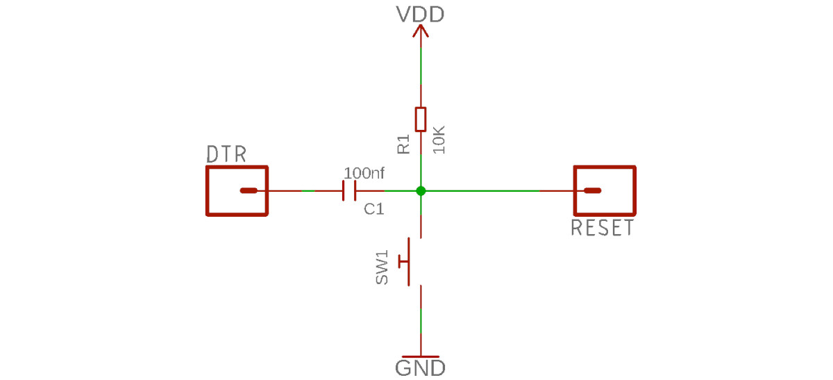
A critical point is the target system's RESET line. Since this line is used as an open-drain, asynchronous half-duplex serial communication line, one has to ensure there is no capacitive load on the line when used in debugWIRE mode. While the debugger tries to recognize such situations before any damage is done, it will certainly not catch all problematic configurations.
Further, there should be a pull-up resistor of around 10 kΩ. According to reports of other people, 4.7 kΩ might also work. And the RESET line should, of course, not be directly connected to Vcc and there should not be any external reset sources on the RESET line. The debugger does not recognize these problems.
If your target system is an Arduino UNO R3 or a similar board, you must be aware that there is a capacitor between the ATmega328's RESET pin and the serial chip's DTR pin that implements the auto-reset feature, as shown in the following picture.
One can disconnect the capacitor by cutting the solder bridge labeled RESET EN on the board (see picture), but then you cannot use the automatic reset feature of the Arduino IDE any longer.
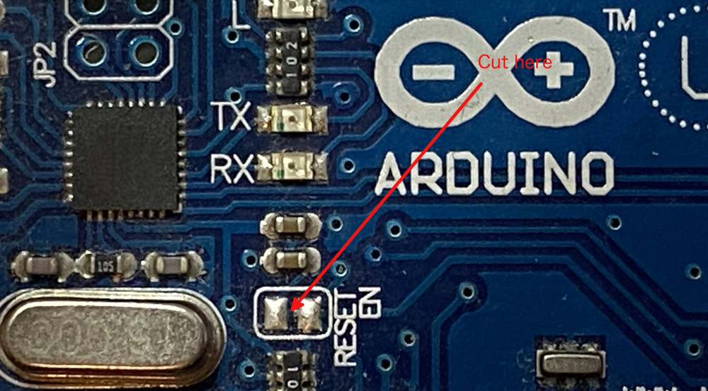
A recovery method is to put a bit of soldering on the bridge or to solder pins to it that can be shortened by a jumper.
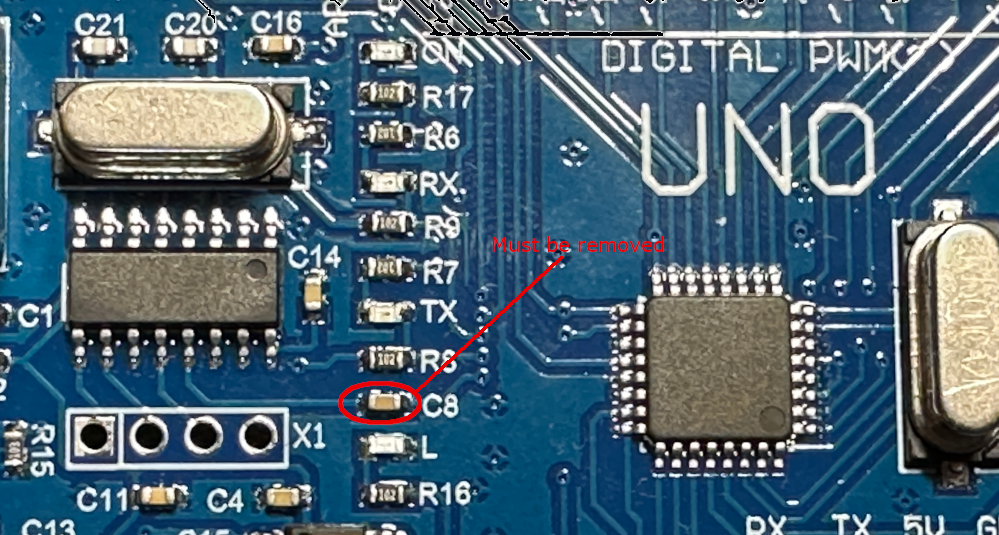
On UNO clones, which have a CH340G chip as the serial interface, there is not such a nice cut-off point. On some of them, it is the C8 capacitor that you have to remove.
Modifications for other Arduino AVR boards are covered on this webpage.
Worst-case scenario
So, what is the worst-case scenario when using debugWIRE? As described in the section on debugWIRE, first, the DWEN fuse is programmed using ISP programming. Then, one has to power-cycle to reach the debugWIRE state, where you can communicate with the target over the RESET line. If this kind of communication fails, you cannot put the target back in a state where ISP programming is possible. And the bootloader will not work either because it had to be erased. Your MCU is bricked.
One way to try to resurrect your MCU is to make the RESET line compliant with the debugWIRE requirements. Then you should be able to connect to the target using the hardware debugger.
The most reliable way to revive your MCU is HV programming, which requires applying 12 volts to the RESET pin and a lot of other things. So you either remove the chip from the board and do the programming offline, or you remove any connection from the RESET line to the Vcc rail and other components on the board. Then, you can use an existing high-voltage programmer or build one on a breadboard.