Preparing a target board for debugging
When you want to debug a program on a target board, usually some modifications of the MCU fuses, the bootloader, and/or hardware are necessary. For this reason, it is a good idea to record the current state and the changes necessary to enable the board for debugging:
- download the current fuse settings (using avrdude),
- download the currently used bootloader (again using avrdude) or make sure that you are able to reinstall the same bootloader, and
- record necessary physical changes on the target board.
With that, it will be easy to restore the original state after debugging, if desired. If you are working in the Arduino context, restoring fuses and the bootloader is something you can delegate to the Burn Bootloader function. However, you should record any physical changes.
You can get some decent development boards from Microchip that contain embedded debuggers, which work well with PyAvrOCD. In this case, preparations and restoring the original state are not an issue.
General considerations
Depending on the type of debugging interface the MCU provides, different actions must be taken to prepare the target board for debugging. The general rule is that the lines used for debugging should not have any resistive or capacitive loads or active components on them.
Sometimes it may be additionally necessary to change a few fuses before debugging is possible. Some of the fuses will be taken care of by the GDB server, provided PyAvrOCD is asked to manage these fuses by a command line option, e.g., --manage dwen, when invoking the GDB server:
Lockbits: If lockbits are set, then debugging is impossible. For this reason, the GDB server will clear the lockbits by erasing the chip's flash (and perhaps EEPROM) memory, provided PyAvrOCD has been instructed to manage the lockbits.BOOTRST: If this fuse is programmed, then instead of starting at address 0x0000, the MCU will start execution at the bootloader address. Since this is usually not intended when debugging, the GDB server unprograms this fuse. For the unlikely case that one wants to debug a bootloader, there is still the option to protect this fuse by not includingbootrstas a fuse to be managed by the server when starting the GDB server from the command line.DWEN: This fuse needs to be programmed to use the debugWIRE on-chip debugger. PyAvrOCD will program this fuse when asked to do so by the commandmonitor debugwire enable. After the fuse has been programmed, you must power-cycle the target board to enable the debugWIRE interface. Note that afterwards, SPI programming is impossible. With the commandmonitor debugwire disable, the debugWIRE interface will be disabled, and theDWENfuse will be unprogrammed. Of course, DWEN programming by PyAvrOCD is only performed if PyAvrOCD is instructed to manage this fuse.OCDEN: This is the fuse for enabling the JTAG on-chip debugger. It is simpler to deal with thanDWEN, because one can enable and disable this fuse in every situation. It will be activated before debugging starts and deactivated afterwards. This happens, of course, only if PyAvrOCD has been instructed to manage this fuse.EESAVE: If this fuse is programmed, then EEPROM contents will survive chip erase operations. If not, EEPROM content is deleted each time an erase operation is performed, even if this is only organizational. If you want to protect your EEPROM content, allow PyAvrOCD to manage this fuse. It will then temporarily program this fuse when necessary in order to safeguard the EEPROM content. This is particularly important when loading an executable that contains a code part to be stored in EEPROM.
If you want to leave all the fuse management to pyavorcd, then just specify --manage all, which is the default with Arduino IDE2. If you want to play it safe, you can manage these fuses and the lockbits manually using a fuse setting program such as avrdude.
Finally, as already mentioned above, bootloaders will be deleted, so they need to be reinstalled after debugging has finished. Additionally, one cannot use the services some bootloaders offer, e.g., writing to flash memory. If you want to debug such a program, you need to set up a mock object.
Preparing a debugWIRE target
Physical preparations
Since the RESET line is used for communication between the MCU and the debug probe, no capacitors should be connected to it. Similarly, pull-up resistors should not be stronger than 10 kΩ. And, there should be no active reset circuit connected to this line. In other words, before debugging starts, disconnect such components from the RESET line.
On the Arduino Uno and similar boards, an auto-reset capacitor is usually connected to the RESET line, as shown below.
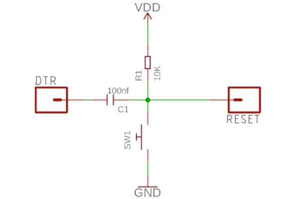
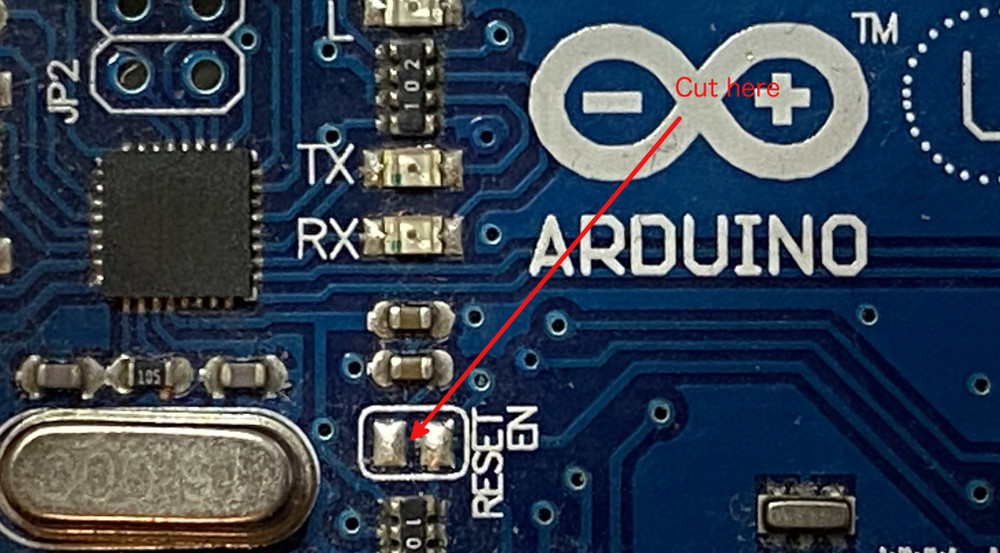
This is responsible for issuing a reset signal when a serial connection is established to the board, which starts the bootloader, which then expects a HEX file sent by the Arduino IDE. On the original Uno board, there is a solder bridge marked 'RESET EN' that needs to be cut to disconnect the capacitor.
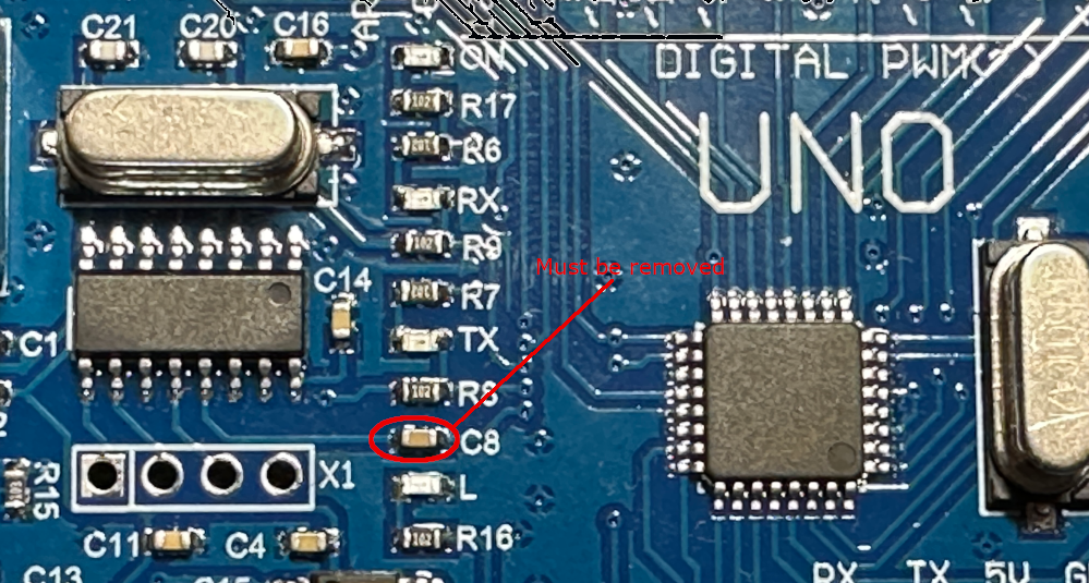
On clone boards with a CH340 serial converter chip, you may have to remove the capacitor marked C8.
Things are a bit more complicated with Arduino Nano boards. Here, you not only have to remove the auto-reset capacitor but also a strong pull-up resistor of 1kΩ on the RESET line. This is impossible for the original boards because the resistor is part of a resistor array. You may try to cut the trace from Vcc to the resistor, but I doubt this can be done without damaging other parts of the board.
For Arduino Nano clones (those using a CH340 as the serial converter), one can remove the resistor and the capacitor, as described by denMike.
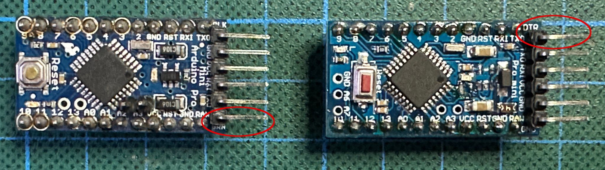
The Arduino Pro Mini is a simpler case. The pull-up resistor has a resistance of 10 kΩ, and the auto-reset capacitor is not connected as long as nothing is connected to the DTR pin. This is the header pin, either labeled DTR or GRN. On the original Sparkfun board (left), this is the bottom pin; on some clones (right), it is the top one.
For other boards with ATmega168 and ATmega328 chips, the situation is similar. Find out what is connected to the RESET line and disconnect any capacitors and strong resistors. And the same holds for other debugWIRE MCUs.
Fuse settings when PyAvrOCD manages the fuse
In almost all cases, you do not need to change any fuses on a debugWIRE target before you can start debugging. One exception is when the RESET pin has been disabled (by programming the RSTDSBL fuse), allowing it to be used as a GPIO. In this case, you need to unprogram this fuse using high-voltage programming. The same holds when SPIEN (enabling SPI programming) is unprogrammed.
The DWEN, BOOTRST, and EESAVE fuses and the lockbits will be taken care of by PyAvrOCD, if this is permitted (see above).
Fuse settings when fuses are managed manually
When you want complete control over the fuses, then make sure that the fuses are set as follows before you invoke the debugger:
-
You may want to program the
EESAVEfuse before the next step in order to save the EEPROM content. -
Clear the
lockbitsby erasing the entire chip. This is necessary because otherwise, debugging is impossible. It will erase any bootloader as well. -
Unprogram the
BOOTRSTfuse, if present and programmed. Otherwise, execution will not start at address 0, but in the bootloader area that has been cleared. -
Program the
DWENfuse. After that, power-cycle the target board.
Now, you should be able to connect to the OCD on the target MCU.
After you have finished debugging and issued the monitor debugwire disable command, you can connect again with an SPI programmer and unprogram the DWEN fuse. Make sure that, in between, power is always applied to the target board because otherwise you may have switched back to debugWIRE mode.
Preparing a JTAG target
Physical preparation
JTAG targets are easier to deal with. Simply do not connect anything to the JTAG lines (TDI, TDO, TMS, TCK) or disconnect those components.
Fuse settings when PyAvrOCD manages fuses
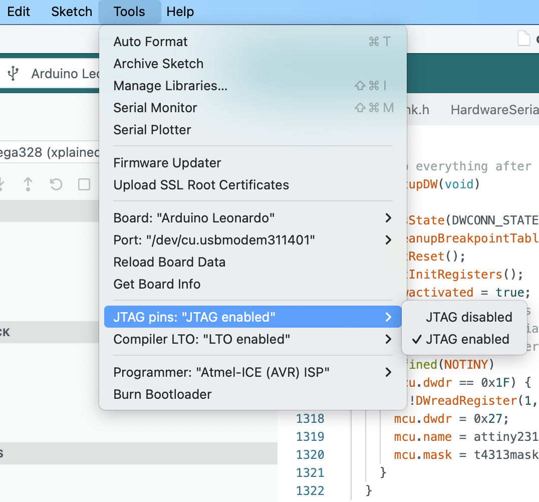
Access to the JTAG pins could be disabled. This is, for example, the case for the Arduino boards. In this case, you need to program the JTAGEN fuse before debugging can start. This has to be done using the SPI programming interface. In the Arduino IDE 2, you can achieve this by setting the JTAG attribute in the Tools menu to enabled and then performing the Burn Bootloader action using SPI programming.
From then on, you can connect to the board using the JTAG connector.
As in the debugWIRE case, it could be that SPI programming has been disabled. If the JTAG pins are enabled, this does not matter because the JTAG pins are all that is needed. If not, high voltage programming is necessary.
The OCDEN, BOOTRST, and EESAVE fuses and the lockbits will be taken care of by PyAvrOCD (see above).
Fuse settings when fuses are managed manually
When you want full control over the fuses, then make sure that the fuses are set as follows before you invoke the debugger. Make sure that the JTAG pins are enabled (see above). Afterward, use avrdude and an SPI programmer as follows:
-
You may want to program the
EESAVEfuse before the next step in order to save the EEPROM content. If you intend to load executables that contain EEPROM contents, you definitely need to program the fuse! -
Clear the
lockbitsby erasing the entire chip. This is necessary because otherwise debugging is impossible. This will erase any bootloader as well. -
Unprogram the
BOOTRSTfuse, if programmed. Otherwise, execution will not start at address 0, but in the bootloader area that has been cleared. -
Program the
OCDENfuse.
Now, you should be able to connect to the OCD on the target MCU.
After you have finished debugging, you should unprogram OCDEN because otherwise no lower-power operation is possible.
Preparing a PDI target
Physical preparation
If the PDI interface is used, then the RESET line will be employed as a clock line. Here, we have the same restrictions as in the case of debugWIRE: no resistive or capacitive load, or active reset circuit, on the reset line.
Fuse settings
The SPIEN fuse could be disabled. In this case, the above comments apply. Otherwise, there is no need to change any fuses before beginning the debugging process.
Preparing a UPDI target
Physical preparations
Ensure that there is no capacitive or resistive load or active component on the UPDI line and that the UPDI pin is accessible.
On the Nano Every, for example, this pin cannot be accessed through the board pins, but there is a pad on the backside of the PCB that can be used to access the UPDI line. And the USB-UART converter is usually disconnected from this pin.
On the Uno WIFI Rev2, again the UPDI pin is not exposed. But on this board, a mEDBG debugger is implemented. So you can connect to this debugger.
Fuse settings
If the UPDI pin is a dedicated UPDI pin, you do not have to prepare anything. If this is not the case, then the pin might have been programmed to act as a GPIO or the RESET line. To enable debugging and programming over this pin again, you will need to use a high-voltage UPDI programmer. Here, you must ensure that the 12 V pulse does not damage any components on your board.